
Dove tecnologia e sostenibilità s’incontrano
Accompagniamo la tua azienda verso la trasformazione digitale sostenibile dei processi di logistica, distribuzione e vendita
Piattaforma digitale .one

La nostra storia inizia in questi mercati, a fianco di aziende che producono, distribuiscono e commercializzano beni di largo consumo, dal lattiero-caseario alle torrefazioni, dai prodotti per la cura della persona e della casa alle aziende cosmetiche e farmaceutiche, al pet food & pet care
La nostra storia inizia in questi mercati, a fianco di aziende che producono, distribuiscono e commercializzano beni di largo consumo, dal lattiero-caseario alle torrefazioni, dai prodotti per la cura della persona e della casa alle aziende cosmetiche e farmaceutiche, al pet food & pet care
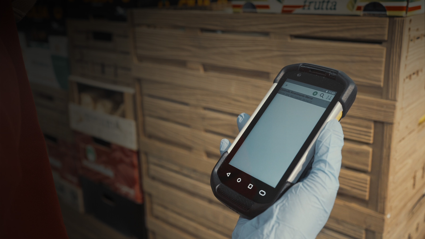
Ci rivolgiamo alle aziende della grande distribuzione organizzata (GDO) e specializzata (GDS) con applicazioni pensate sia per catene di punti vendita diretti, sia per affiliati o indipendenti (franchising)
Ci rivolgiamo alle aziende della grande distribuzione organizzata (GDO) e specializzata (GDS) con applicazioni pensate sia per catene di punti vendita diretti, sia per affiliati o indipendenti (franchising)

Collaboriamo con le principali aziende italiane ed internazionali di abbigliamento e calzature, lusso e sport, occhialeria ed accessori, profumeria e gioielleria, che distribuiscono attraverso i vari canali di vendita: retail, wholesale, web, agenti
Collaboriamo con le principali aziende italiane ed internazionali di abbigliamento e calzature, lusso e sport, occhialeria ed accessori, profumeria e gioielleria, che distribuiscono attraverso i vari canali di vendita: retail, wholesale, web, agenti
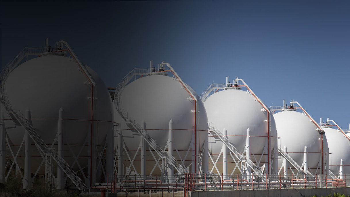
Ci affianchiamo alle principali aziende italiane e internazionali che distribuiscono GPL, gas tecnici e medicali, accompagnandoli in tutto il processo di monitoraggio consumi e diagnostica, vendita, distribuzione, post vendita e gestione della relazione con l’utente finale
Ci affianchiamo alle principali aziende italiane e internazionali che distribuiscono GPL, gas tecnici e medicali, accompagnandoli in tutto il processo di monitoraggio consumi e diagnostica, vendita, distribuzione, post vendita e gestione della relazione con l’utente finale
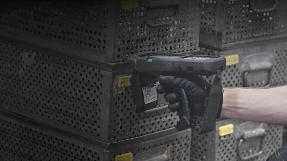
Le nostre esperienze, soluzioni e servizi spaziano in contesti industriali diversi, dal settore metallurgico alla produzione di materie plastiche, dal settore automobilistico all’aerospaziale
Le nostre esperienze, soluzioni e servizi spaziano in contesti industriali diversi, dal settore metallurgico alla produzione di materie plastiche, dal settore automobilistico all’aerospaziale

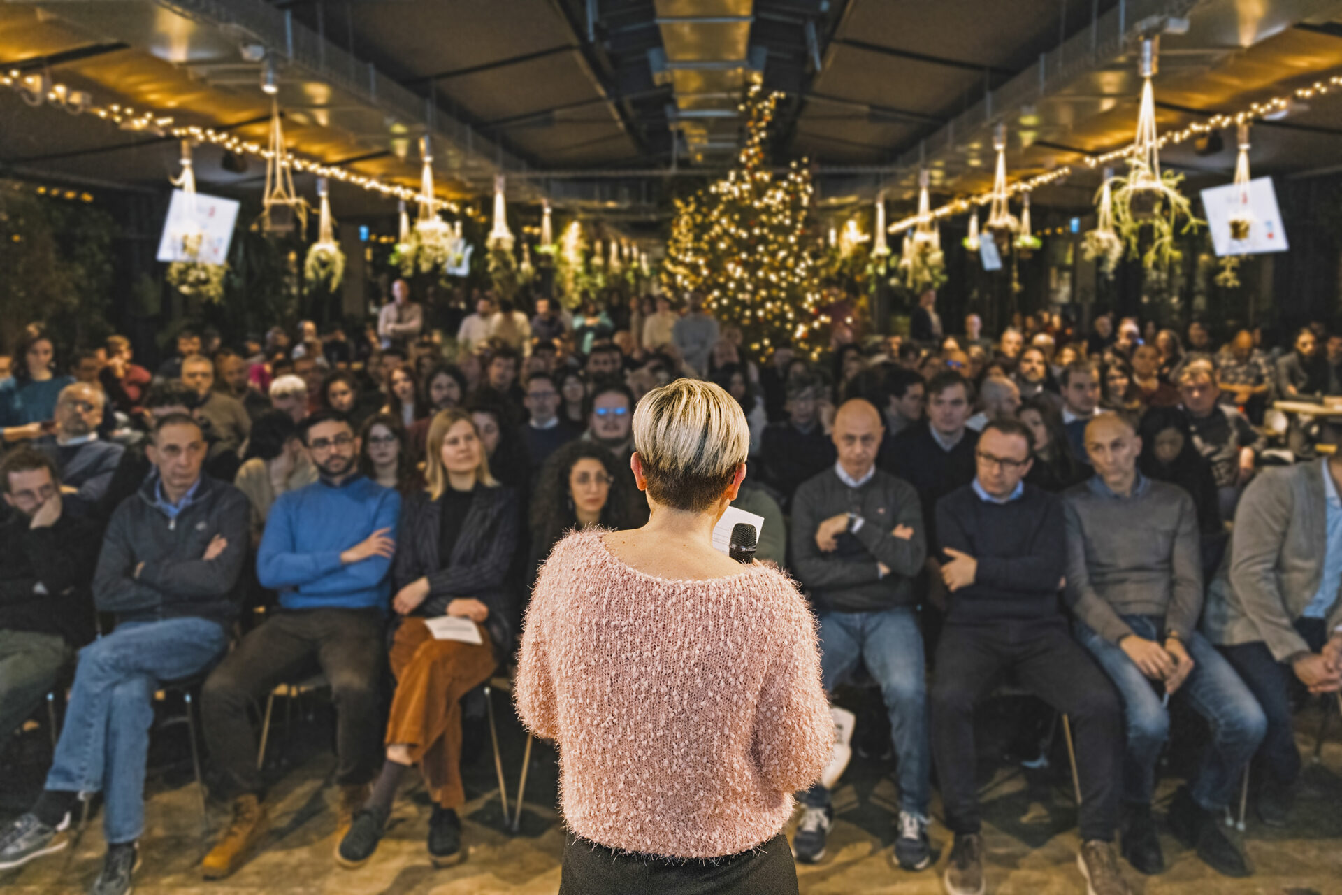
Ci chiamiamo atonpeople perché condividiamo non solo lo spazio e il tempo del nostro lavoro quotidiano, ma anche il senso di appartenenza ad una squadra che è in campo per crescere insieme, realizzando la versione migliore di ciascuno.
Le nostre esperienze raccontate dalle persone, un punto di vista ribelle perché vogliamo stare dalla parte dei clienti, delle persone, dell’ambiente, costruire insieme un futuro migliore per tutti remando nella stessa direzione.
Sfoglia Atonews


